ROB SEWARD :: WORKS BIO CONTACT BLOG
Make your own True Random Number Generator 2
Attention: I've recently created Z1FFER, an open-source RNG Arduino shield. You can learn more and purchase at openrandom.org. DIY plans are also available.
Contents
- Intro
- Notes on the New Design
- The Circuit
- How it Works
- Part List
- The Code
- Photos
- Performance Discussion
- Wish List
Intro
This generator uses avalanche noise, and is based on designs by Will Ware and Aaron Logue. Herein are instructions as to how you can use Arduino to analyze a noise source and output random data serially.
There are two types of random numbers: true and pseudo. Pseudo random numbers are created by an algorithm. The problem with this is that if someone knows what algorithm you use, it is theoretically possible to predict what numbers you will create. True random number generators create sequences that are impossible to predict. They use random physical phenomenon as their source of randomness. They are used for encryption and Princeton's far-out micro psychokinesis research. If you are considering using this generator for encryption, please take a look at the discussion section.
Notes on the New Design
The previous RNG had a problem: after about 3 months of use the noise signal would drift and the ratio of 0s and 1s would go out of balance.
While trying to debug this problem I redesigned the whole board. My redesign was based off of Aaron Logue's design. It functions on the same principle as the first RNG, except it uses fewer components and there is no signal interference from the RS232 chip.
Even with the new design, however, the new RNG started to behave just like the old one. After 3 months the output became not random. I was just about to build a new board from scratch, when it dawned on me that the signal (even though it looked OK on the oscilloscope) may have changed and caused the ratio of 0s and 1s to drift. I suspect component (or board) aging was the culprit. It's possible that the "tunneling electrons" are damaging the transistors, causing the drift. (Thanks Warren Hays.)
So I wrote a program that calibrates itself. Thus if the signal changes, the micro-controller adapts. It fixed the problem.
I also rewrote everything for Arduino. The Arduino API is better designed than the PIC libraries I've used (I've tried MPLAB ICD 2, PIC C, and PicBasic), way cheaper, and as far as I can tell, every bit as capable. Also it's open source. And, if you have a breadboard and the parts, you can assemble the circuit very quickly. I've also designed a breakout board. I haven't built it yet, but if you are feeling adventurous you can download the PCB files here.
The Circuit
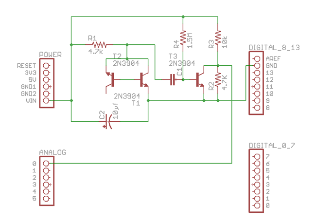
How it Works
The two transistors with their bases touching create "avalanche noise in a reverse-biased PN junction." This noise is amplified by the third transistor, and sent across a voltage divider to Arduino. On the oscilloscope, the signal looks very fuzzy. In software, that randomness is converted into a stream of 1s and 0s.
The code works like this: for the first 10 seconds, record the signal from the circuit on the analog input pin. Find the median. Then for each subsequent reading of the input pin, see if it is above or below the median. If it is above, output a 1, if it is below, output a 0. Filtering can be applied to the output stream of 1s and 0s to reduce bias.
Part List
| Component | Quantity |
|---|---|
| Arduino | 1 |
| 2N3904 Transistor | 3 |
| 4.7k Resistor | 2 |
| 10k Resistor | 1 |
| 1.5M Resistor | 1 |
| 0.1µf Capacitor | 1 |
| 10µf Capacitor | 1 |
| Breadboard | 1 |
| 12v DC Adapter | 1 |
The Code
![]()
The code implements both XOR and Von Neumann filtering to reduce bias in the output. Von Neumann supposedly offers the best bias removal but it slows the output by a factor of 2. You can also change the format of the output. That is, you can print out 0s and 1s in either binary or ASCII. To configure the filtering and the output, just change the constants at the top of the file.
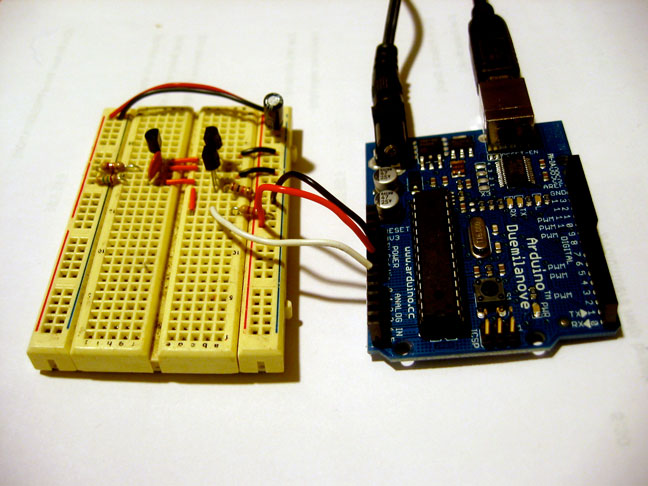
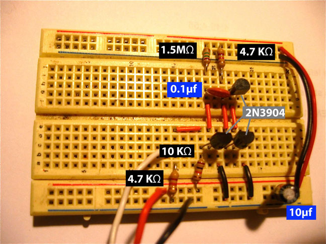
Photos
Performance Discussion
NOTE: While the numbers this device produces may or may not be usable for encryption, the overall design is not secure. If an attacker were to gain access to a connected computer, they could, by using the Arduino bootloader, upload their own code and have the generator produce whatever results they wanted. Better RNGs are designed to fail if they are tampered with.
I have not done a thorough analysis of the quality of the random bits. Other people have, however. There's a good discussion of the output here:
http://forum.arduino.cc/index.php?topic=161682.0
In summary, the performance does not exceed that of /dev/random but with more whitening, better calibration, and perhaps the integration of more noise sources it may be possible.
Also, Walter Anderson studied the drift of the noise source over 10 months:
http://code.google.com/p/avr-hardware-random-number-generation/wiki/AvalancheNoise
Wish list
- Test results. (Perhaps I can systematically collect them in the github repo.)
- Design that integrates multiple noise sources.
- Improved whitening methods.
- Confirmation of the viability of my PCB designs.
- A better solution for compensating for the noise source's drift. The device currently calibrates itself only on startup. It would be better if calibration could be continuous without interrupting the bitstream.
Please feel free to contact me if you have any questions, experimental results, etc.

This work is licensed under a
Creative Commons Attribution-NonCommercial 2.5 License
.